
Example multicast destination NAT (DNAT) configuration
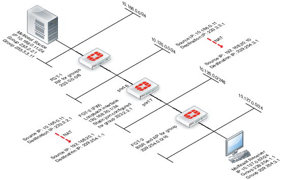
The example topology shown and described below shows how to configure destination NAT (DNAT) for two multicast streams. Both of these streams originate from the same source IP address, which is 10.166.0.11. The example configuration keeps the streams separate by creating 2 multicast NAT policies.
In this example the FortiGate units have the following roles:
- FGT-1 is the RP for dirty networks, 233.0.0.0/8.
- FGT-2 performs all firewall and DNAT translations.
- FGT-3 is the RP for the clean networks, 239.254.0.0/16.
- FGT-1 and FGT-3 are functioning as PM enabled routers and could be replaced can be any PIM enabled router.
This example only describes the configuration of FGT-2.
FGT-2 performs NAT so that the receivers connected to FGT-3 receive the following translated multicast streams.
- If the multicast source sends multicast packets with a source and destination IP of 10.166.0.11 and 233.2.2.1; FGT-3 translates the source and destination IPs to 192.168.20.1 and 239.254.1.1
- If the multicast source sends multicast packets with a source and destination IP of 10.166.0.11 and 233.3.3.1; FGT-3 translates the source and destination IPs to 192.168.20.10 and 239.254.3.1
Example multicast DNAT topology
To configure FGT-2 for DNAT multicast
- Add a loopback interface. In the example, the loopback interface is named
loopback.
config system interface
edit loopback
set vdom root
set ip 192.168.20.1 255.255.255.0
set type loopback
next
end
- Add PIM and add a unicast routing protocol to the loopback interface as if it was a normal routed interface. Also add static joins to the loopback interface for any groups to be translated.
config router multicast
config interface
edit loopback
set pim-mode sparse-mode
config join-group
edit 233.2.2.1
next
edit 233.3.3.1
next
end
next
- In this example, to add firewall multicast policies, different source IP addresses are required so you must first add an IP pool:
config firewall ippool
edit Multicast_source
set endip 192.168.20.20
set interface port6
set startip 192.168.20.10
next
end
- Add the translation security policies.
Policy 2, which is the source NAT policy, uses the actual IP address of port6. Policy 1, the DNAT policy, uses an address from the IP pool. The source and destination addresses will need to be previously created address objects. For this example, 233.3.3.1 255.255.255.255 will be represented by "example-addr_1" and 10.166.0.11 255.255.255.255 will be represented by "example-addr_2". You will likely want to use something more intuitive from your own network.
config firewall multicast-policy
edit 1
set dnat 239.254.3.1
set dstaddr example-addr_1
set dstintf loopback
set nat 192.168.20.10
set srcaddr example-addr_2
set srcintf port6
next
edit 2
set dnat 239.254.1.1
set dstaddr 233.2.2.1 255.255.255.255
set dstintf loopback
set nat 192.168.20.1
set srcaddr 10.166.0.11 255.255.255.255
set srcintf port6
next
end
- Add a firewall multicast policy to forward the stream from the loopback interface to the physical outbound interface.
This example is an any/any policy that makes sure traffic accepted by the other multicast policies can exit the FortiGate unit.
config firewall multicast-policy
edit 3
set dstintf port7
set srcintf loopback
next
end
Copyright © 2018 Fortinet, Inc. All Rights Reserved. | Terms of Service | Privacy Policy
